
Smart House
Heating and air conditioning control
Setting the heating control in the system
Smart Home Larnitech
The authors of the instructions Roman Polotsky and Nikolai Rusanov
Smart Home Larnitech
The authors of the instructions Roman Polotsky and Nikolai Rusanov
In this article, we will consider separately the issues of controlling heating and air conditioning in an apartment or a country house, through the equipment of the Larnitech Smart Home system. The "climate control" mode, which allows you to set up a single climate system from several elements of heating, cooling, humidification and ventilation in the room, we will consider in a separate article.
Larnitech offers one of the most convenient and complete control systems among the Smart Home systems on the market, moreover, with the simplest setup and adjustment.
Larnitech offers one of the most convenient and complete control systems among the Smart Home systems on the market, moreover, with the simplest setup and adjustment.
How a home automation system controls the climate
Larnitech Smart Home System controls the following devices:
- electric or water radiators (as well as infrared heaters, warm ceilings, etc.)
- electric or water heated floors
- air conditioners
Also, at some facilities, the issue of interaction with the boiler, control of air humidity and ventilation according to the level of carbon dioxide in the room (CO2) may arise.
Consider these heating methods and their control settings.

Water heating
To control a water radiator or underfloor heating, a servomotor must be installed with a seat that matches the radiator or manifold valve. As a rule, this is M30x1.5.

If a collector is installed in a house or apartment, and the radiators of each room are connected to a separate collector circuit, then it is easier and more convenient to install drives not on radiators, but on collector circuits. This is more convenient because the drive control cables do not need to be led to each radiator and the output points must be determined in advance so that the cable is the most invisible, but can be led into the collector. For heating drives, cables 2x0.75 or similar are mounted. The drive supply voltage is 230 volts AC.
To control water heated floors, the drives are similarly installed on the collector of underfloor heating.

The actuator controls the supply of hot water to the heating circuit. Since the room (especially underfloor heating) is a rather inert system in terms of heating, frequent switching on and off of heating does not lead to noticeable temperature fluctuations.
As a control module, you can use the relay output of any Larnitech module, including both DIN rail modules and modules for installation in a socket. The main heating control module is DW-HC10.B.

The module has 10 relay outputs for connecting heating drives, the current of each output should not exceed 0.5 amperes, that is, 110 watts. The relays are quiet (this is important when the switchboard is located near living rooms, where switching clicks should not be heard) and are designed for a large number of switching cycles over several years of operation. The current consumption of the drive to the radiator or collector of the warm floor does not exceed 250mA. Up to 12 1-wire temperature sensors can be connected to the module, each sensor is connected with a separate wire (loop is not allowed).
You can also use the BW-LC02 module. A 1-wire temperature sensor, two controlled devices with a current consumption of up to 2 amperes (440 watts) or up to 6 any elements with a discrete output (switches, motion or door opening sensors) are connected to it.

Also this module (or input module BW-SW06) can be used as a gateway for a floor sensor if the distance to the panel is too far to use the 1-wire protocol. The module is installed in a socket near the floor, from which the FW-FT sensor is lowered into the floor in a tube. A cable is mounted from the module to the underfloor heating control drive.

Also, temperature sensors can be connected to the inputs of the Metaforsa MF-14 and MF-10 controllers. Included with the controller are 4 temperature sensors, it is possible to connect 8 sensors. Thus, the Metaforsa controller can control 8 heating zones.
The 7-channel expansion module DW-HT07 can act as a heating controller. It has 7 relays, 12 discrete type inputs and 8 inputs for connecting 1-wire temperature sensors
When installing cables for 1-wire sensors, remember that the 1-wire bus is extremely sensitive to interference. Sensors should be connected with a shielded twisted pair cable (category 5 or 6 with shield grounding), keeping the distance to the power cables at least 100mm and the total cable length from the controller to the sensor up to 30m.
1-wire temperature sensors can be connected to Metaforsa and DW-HT07 controllers by a loop, that is, all temperature sensors in parallel on one cable (without branches from a common bus). For BW-LC02, DW-HC08 and DW-HC10 modules, it is only possible to connect one 1-wire sensor to one connector, that is, each sensor is connected to the module with a separate cable.
Electric heating
The control of an electric heater of any type (radiator, convector, IR heater, warm ceiling) is carried out by supplying voltage to the heating device through a relay (usually the relay is located in the electrical panel).
The control principle is the same - turning the appliance on and off to maintain the set temperature.
Electric heaters differ from water heating drives in their high power consumption, usually not less than 500 watts. Therefore, heaters cannot be connected directly to the outputs of the BW-LC02 or BW-HC10.B modules. To connect electric heaters and electric underfloor heating, it is required to use power relays with a 230 volt coil or contactors that are suitable for the power of the controlled device. You can also connect heaters with a power of not more than 3500 watts to the relay outputs of the DW-LC07.B, DW-LC10.B and DW-LC18.B modules.
Directly to the output of the BW-LC02 module, you can connect an electric underfloor heating with a power of up to 440 watts, this is from 2 to 3 square meters, depending on the power of the heated floor. It is possible to install a small additional relay in the socket, but it is advisable to use the socket next to the BW-LC02 so that the relay does not overheat and does not affect the operation of the floor temperature sensor.
When connecting convectors with active air exchange (that is, with fans), we use relays to control the rotation speed, which are linked in the system as a type of Fancoil relay.
Air conditioners
There are two ways to control air conditioners: through an IR transmitter and through a gateway using the modbus protocol.
To control via an IR transmitter, it is required that the air conditioner has an infrared receiver, for wall-mounted units of the air conditioner this is not a problem, in the case of ceiling-mounted units (channel or cassette), there may not be an IR receiver. Either it will need to be purchased separately, or use modbus as a control method.
This video demonstrates the control of a Daikin air conditioner using the IR commands transmitted by the CW-MLI sensor. Daikin's IR commands are included in the Larnitech system in such a way that the control of the air conditioner from the application completely repeats the control from the standard remote control.
The IR transmitter is built into the CW-MLI motion and light sensor, CW-HTMLII and CW-CO2 sensors.

The system learns control commands from the complete air conditioner remote control or, if the air conditioner is in the Larnitech database, just select the desired model in the setup interface. To learn control commands, an IR receiver is required, it is on the DE-MG controller case and is not available on Metaforsa. If you need to configure the remote control and use the Metaforsa controller, you can temporarily take the DE-MG from a Larnitech representative to teach the system commands, and then disconnect it from the system.

Current list of supported air conditioners for IR control that do not require separate training.
Click to enlarge.
Click to enlarge.
It is important to understand that control via infrared commands has no feedback. That is, the transmitter sends a command to the air conditioner, but does not receive information about whether this command was received or executed. Therefore, it is convenient if in this case the air conditioner itself has an indication of the temperature that is set.
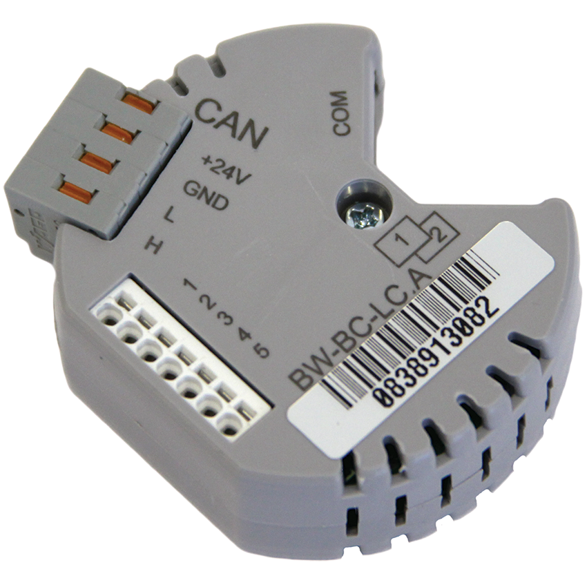
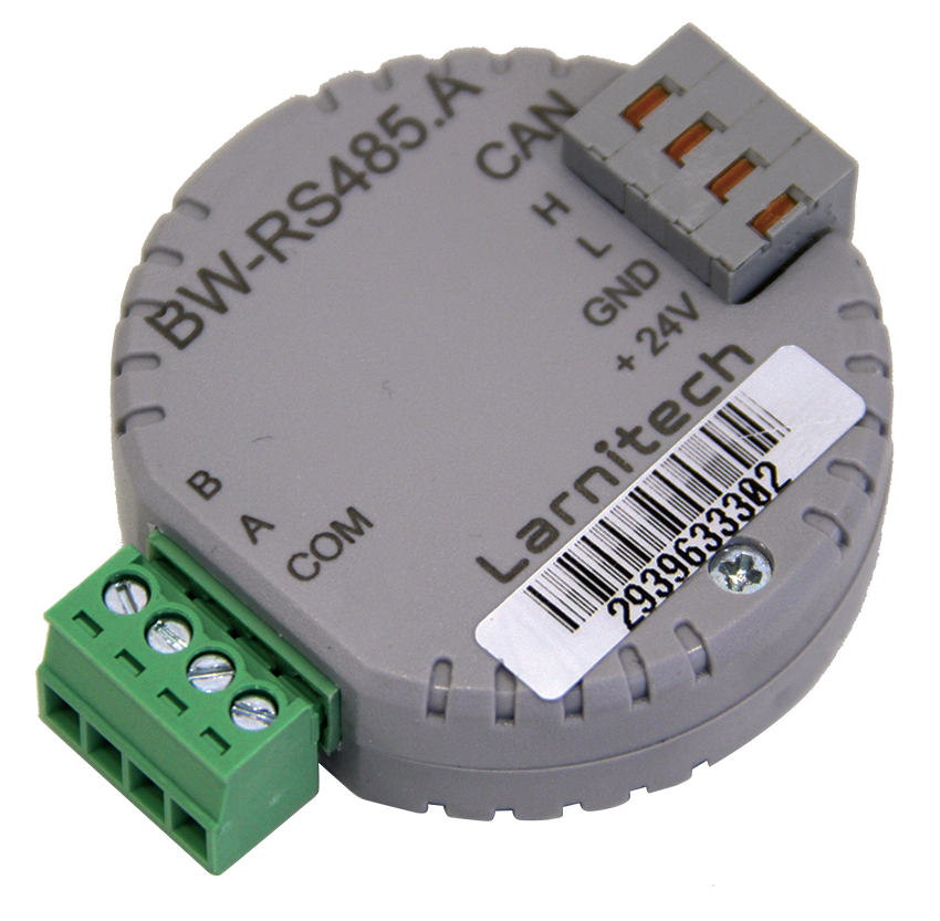
Full feedback control is carried out through specialized controllers, according to the protocol. Intesis modules are most often used, for example, for Mitsubishi air conditioners, this is the IntesisBox ME-AC-MBS-1 module, by the number of indoor units of air conditioners. Integration requires a Larnitech DW-RS485 or BW-RS485 module.
Another option is the Coolmasternet module from the Coolautomation campaign, it is used for VRF or VRV systems, one module per system is required. In this case, the integration takes place via TCP/IP.
When controlled through the controller, the Larnitech system will receive its status from the air conditioner and control the execution of commands. These controllers are compatible with hundreds of models of air conditioners, but it is better to ask the manufacturer in advance about compatibility.


Temperature sensors
To control the heating in the room, it is necessary to have an air temperature sensor in it. This can be a 1-wire sensor connected to the DW-HC10.B module (DW-HC08), to the MF-14 controller, or to socket-mounted input modules (eg BW-SW06, BW-LC02). Most often, these sensors are located behind standard mechanical switches.
It can also be tire sensors CW-CO2, CW-HTMLI, WW-HTL. It is recommended to install the air temperature sensor on the wall at a height of 900 to 2000 mm from the floor, do not block it with furniture or curtains, remove it from heating appliances and heating household appliances (for example, a TV).
Often, panels with built-in KNX or HDL Buspro temperature sensors are used to measure air temperature, or Siemens modbus panels can also be used.
The outdoor temperature sensor can be installed, firstly, to display the outdoor temperature in the Larnitech application, and secondly, to implement any control algorithms. Usually, 1-wire FW-FT sensors with IP65 protection level are used for this.
Another option to get street weather is to install the free Weather plugin, which gets temperature, wind speed and other parameters from a server on the internet. These options can be used when setting up automation.
Another option to get street weather is to install the free Weather plugin, which gets temperature, wind speed and other parameters from a server on the internet. These options can be used when setting up automation.
If it is necessary to control an electric underfloor heating, it is required to install a floor temperature sensor FW-FT. When heating with a water-heated floor, a floor temperature sensor is optional, but desirable. The optional installation of a floor temperature sensor is due to the fact that the temperature of the coolant in the floor may not be high enough to heat the floor above the maximum allowable values (usually not higher than 26-28 degrees), and the air temperature sensor will not allow overheating of the air. But then it will not be possible to realize the possibility of keeping the floor constantly warm, so it is advisable to install a floor sensor.

Communication with the boiler
Since the system controls actuators on the collectors or on the radiators, boiler control is not required. But most boiler models have a control interface for the ability to switch its operating mode (for example, "comfort" or "economy"). Below are two main options for integration with the boiler:
The boiler may have several "dry contact" outputs to indicate the operating mode or error. For integration in this case, you can use the BW-LC02 module or other I/O modules. BW-LC02 has 6 digital inputs, 2 outputs, temperature sensor connection. The temperature sensor can be fixed on the pipe to control the temperature of the water leaving the boiler
The boiler can be compatible with the RS485 protocol in the Modbus RTU version, which is connected to the Larnitech system via an interface. In this case, you can set up registers for monitoring alarms, send commands to turn on, turn off, save mode, and others.
System Setup
When configuring the Larnitech controller, the output that controls any heater is configured as a heating (or heating) valve.

If a normally open heating actuator is used (such actuators are recommended for radiators), then select Heating valve normally open. That is, for heating it is not required to apply voltage to it, but for cooling the room it is required. The normally closed heating valve is selected for any electric heaters, including underfloor heating.
After selecting the output type, the corresponding number of thermostat elements will appear in the climate control section of the application:
After selecting the output type, the corresponding number of thermostat elements will appear in the climate control section of the application:

Now about the sensors - when connected to the system of 1-wire temperature sensors or temperature sensors on the CAN bus, they appear in the room climate control section of the Unit. In order to determine which physical sensor is found in the system, they must either be connected one at a time and immediately renamed, or heated and searched for a sensor with an increased temperature.

Next, to configure the control, you need to create a binding between the heater relay and the temperature sensor. To do this, go into edit mode and long press on the thermostat you need. Select Sensors from the top menu.

Select the sensor that we want to associate with the thermostat and save the link. If multiple sensors are selected, the average value will be used.
In the menu that appears on the button in the upper right corner of the screen, the item Heating mode is available. In manual mode, the relay is turned on and off manually from the application, without being guided by the sensor readings. In Eco, Comfort and Hot modes, you can select the desired temperature, it will be maintained by the system.

In all modes except Manual and Always off. you can set the desired temperature, which will be maintained automatically.

To add an air conditioner controlled via modbus or an IR transmitter to the system, you need to press the Add air conditioner button in the web interface in the Scenarios menu item. Next, you need to specify the name of the air conditioner, the corresponding IR transmitter and the room.

The air conditioner control will then appear in the selected room.

For the air conditioner, not only the temperature is available, but also the position of the curtains, mode, fan speed.
Humidity and CO2 sensors
Humidity and carbon dioxide sensors are included in CW-CO2, humidity sensors are CW-MLI, CW-HTMLI. Similar to air temperature sensors for humidity and carbon dioxide sensors, we create associations in the relay, while the sensor turns the relay on and off depending on the desired and current level.
For the humidity sensor, the actuating device can be a household humidifier plugged into an outlet, or a more professional duct-type model.
For the CO2 sensor, the actuator is forced ventilation. It is possible to set up several stages of the plant operation speed by specifying the type of Fancoil relay outputs.
Climate control methods
The user of the system has the following options for controlling the climate in the house:
1. From the Larnitech app on your smartphone or tablet
2. By voice through voice assistants Alice, Siri, Google Assistant or Alexa
3. From a stationary wall-mounted touch panel. They are often used iPads in a wall frame or Larnitech LCP-10 wired panels with POE power.
4. Control from HDL Buspro or KNX standard wall panels. The Larnitech system integrates with this equipment using ready-made plugins. Siemens thermostats operating on the modbus protocol are also supported.
5. According to pre-programmed scenarios and schedules. For example, at 9 a.m. on weekdays, electric underfloor heating and ventilation are not turned off, from 5 p.m. everything is turned on for heating and ventilation. You can set the intensive airing of the premises for half an hour, then cooling with air conditioning or heating.
Scheduled work
To set the heating or underfloor heating according to the schedule, you need to turn on the Edit Mode and hold your finger on the thermostat for controlling the heating device (or fan, humidifier, underfloor heating). Then select the Auto tab. There you can set the temperature for the Eco, Hot and Comfort modes, as well as create time intervals in which the thermostat switches to the set temperature.
To create an interval, click on the button with the + sign, then edit the added interval.

Setpoint - temperature setpoint, that is, its set value. Work from - the time at which the thermostat switches to this mode, Work till - the end time of the mode. The days of the week are also displayed. Thus, we create as many schedules as required.
If the Weather plugin is enabled, you can use the sunrise-sunset parameters for the selected city in the schedules

Additional features, including scripts and scripts, as well as a unique "Climate Control" mode that combines various indoor climate elements, will be described in the next article.
